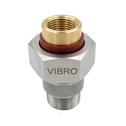
Description


VIBRO CLIP Resilient Sound Isolation Clip provides a professional level of acoustic separation of walls and ceilings. This engineered clip forms a decoupled assembly that does not allow sound vibration to pass through structural connections, which significantly enhances sound transmission class ratings in residential and commercial areas.
The clip system operates through the isolation of drywall and structural framing in a mechanical manner, breaking the direct contact that enables the transmission of noise between rooms. VIBRO CLIP, when properly installed, will convert ordinary construction into high performance acoustic barriers capable of stopping airborne sound as well as structure borne vibration. Installation is easy and economical as compared to other forms of isolation. The clips are directly connected to the existing studs or joists, and they support strong channels that carry finishing materials. This floating assembly is independent of the main structure and it absorbs the vibration energy before it can pass through walls or ceilings. VIBRO CLIP is the best in the management of impact noise, mechanical vibration and overall sound transmission between the adjacent spaces. The system is applicable in home theaters, recording studios, multi-family housing, offices, and any other application where high acoustic isolation is needed. Its strong construction means that it will not deteriorate with time and the streamlined design will fit perfectly into the normal construction programs. To builders and property owners who are interested in a soundproofing solution that can be relied upon to provide a quantifiable acoustic solution, VIBRO CLIP offers a proven performance at reasonable prices.


